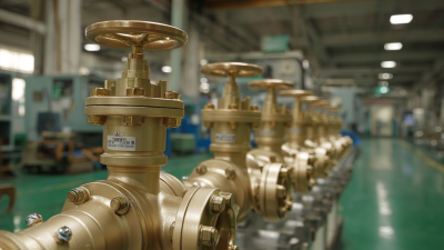

A Flow Regulator Valve controls the movement of liquids or gases through a pipeline. It helps maintain a stable flow rate when pressure changes, equipment demand shifts, or downstream conditions vary. In practical systems, this control can protect pumps, reduce process waste, and improve product consistency.
Inside the valve, a sensing element detects changes in flow, pressure, or both. The valve then adjusts its opening to restrict or permit more media. Some designs use a spring-loaded mechanism, while others rely on pneumatic or electronic control. Picture water entering a narrow pipe and meeting a movable gate. A small adjustment can noticeably change the outlet flow.
The working principle may seem simple. Real installations are less forgiving. Valve sizing, fluid temperature, viscosity, and pipe layout all influence performance. Incorrect selection can cause noise, vibration, pressure loss, or unstable regulation. Engineers therefore review operating data, manufacturer specifications, and applicable industry guidance before installation. Field experience also matters, because a valve that performs well in a test environment may behave differently after months of service.
This guide explains the main valve types, internal components, operating principles, and common applications. It also discusses selection, installation, maintenance, and troubleshooting considerations. No single valve suits every system. That point is easy to overlook. Readers should verify technical details with qualified professionals and current product documentation before making a final decision.
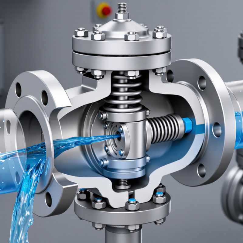
A flow regulator valve controls liquid movement by changing its internal opening. A wider passage usually increases flow. A narrower passage reduces it. The key value is Cv, the valve flow coefficient. Cv represents the water flow, in US gallons per minute, that passes through a fully open valve with a 1-psi pressure drop. This uses water near standard reference conditions. That basis matters.
For liquid sizing, engineers often use Q = Cv√(ΔP/SG). Here, Q is flow rate, ΔP is pressure loss across the valve, and SG is specific gravity relative to water. A fluid with SG of 1 behaves like water in this comparison. Heavier fluids require more pressure for the same flow. The equation is useful, but it is not a complete model. Viscosity, fittings, valve position, and unstable pressure can change the result. Real piping rarely behaves perfectly.
Tips: Confirm the units before calculating Cv. A 1-psi pressure drop is the reference, not always the operating condition. Measure pressure directly upstream and downstream when possible. Check whether the valve is regulating flow or merely limiting pressure. A quick field test can reveal problems that a spreadsheet misses. I have seen sizing errors begin with one overlooked unit conversion. Recheck the square-root relationship, because doubling pressure does not double flow.
A flow regulator valve maintains a target fluid flow through a pipe or process line. It does not control flow by guesswork. The working sequence begins with a setpoint, such as 40 liters per minute. This target is entered into a controller or adjusted manually. A flow sensor then measures the actual rate moving through the line. Its signal returns to the controller for comparison. Small errors matter.
If the measured flow falls below the setpoint, the controller sends a correction signal to the actuator. The actuator may use pneumatic pressure, electricity, or hydraulic force. It moves the valve stem, changing the opening inside the valve. A wider opening usually permits more fluid to pass. A narrower opening restricts the flow. The sensor checks the new condition, creating a continuous feedback loop.
The sequence sounds simple, but real systems are less tidy. Sensor readings can lag during sudden pressure changes. Valve friction may also delay movement, especially after long service periods. In field testing, technicians often compare the displayed flow with an independent meter. That step can reveal calibration drift. A valve can appear to respond correctly while controlling the wrong value.
Good practice includes checking signal wiring, actuator travel, and pressure conditions before changing the setpoint. Manual adjustments can help, but they may hide a deeper control problem.
What Is a Flow Regulator Valve and How Does It Work?
A flow regulator valve adjusts fluid movement to maintain a desired rate or pressure. It responds to pressure changes, manual settings, or an external control signal. In practical systems, the valve opening creates resistance, much like narrowing a water hose. Globe regulators offer accurate throttling and stable control. Their curved internal path, however, creates noticeable pressure loss. Ball regulators use a rotating, drilled sphere. They open quickly and provide low resistance, but precise adjustment can be difficult at very low flow rates.
Needle regulators use a tapered stem and a small opening. They suit clean fluids, instrument lines, and fine flow adjustment. Their narrow passages may clog when particles enter the system. Diaphragm regulators separate the controlled fluid from the operating mechanism. This design supports hygienic or corrosive applications and reduces leakage risk. The flexible diaphragm can wear, especially under frequent pressure cycling.
Valve selection depends on fluid viscosity, temperature, pressure range, cleanliness, and required accuracy. A common mistake is choosing by pipe size alone. A correctly sized globe valve may outperform an oversized ball valve during partial opening. Field technicians should check pressure readings before and after the valve, not just the flow display. That check often reveals hidden restrictions. No design wins every situation. Even needle valves can behave poorly when installation orientation, seals, or calibration receives little attention.
A flow regulator valve changes its opening to maintain a target flow or pressure. A sensor, actuator, and controller usually work together. The valve itself only creates a controlled pressure drop. For liquid service, IEC 60534-2-1:2011 defines sizing methods using flow rate, pressure drop, and specific gravity. In common US units, Cv = Q√(SG/ΔP). Here, Q is gallons per minute, SG is specific gravity, and ΔP is pressure drop in psi. For 100 gpm of water with a 4 psi drop, the estimated Cv is 50. The arithmetic is simple. The selection is not. Pipe reducers, viscosity, flashing, and operating range can change the result.
Gas sizing requires more caution. Pressure ratio, absolute pressure, temperature, compressibility factor, and expansion factor affect capacity. IEC 60534-2-1 and ISA 75.01.01 address these corrections. Choked flow begins when downstream pressure falls below the critical pressure ratio. Further pressure reduction then produces little additional flow. The valve may sound harsh, vibrate, or suffer rapid trim damage. A practical check includes the valve’s xT or FL factor, depending on service and calculation method. The International Energy Agency’s Energy Efficiency 2023 report estimates that industry consumes about 37% of global final energy. That broad figure makes unnecessary valve pressure loss worth investigating. Still, a report cannot replace field measurements. I would verify density at operating temperature, not at laboratory conditions. A spreadsheet can mislead. Recheck the worst-case flow, minimum inlet pressure, and required turndown before approving the final size.
A flow regulator valve controls fluid movement by adjusting its opening as pressure or flow changes. A sensing line measures downstream conditions, while a diaphragm, piston, or actuator moves the valve plug. The smaller opening reduces flow; the larger opening restores it. Response depends on spring setting, fluid density, and pressure drop. Small details matter.
ASME B16.34 Classes describe pressure-temperature ratings, not a valve’s flow capacity. Class 150, 300, and higher ratings must be checked against the valve material and operating temperature. A rating that looks adequate at room temperature may fall at elevated temperature. Body, trim, stem, bolting, and gasket materials also need compatibility with the fluid and corrosion conditions. Carbon steel may suit general service, while stainless alloys can offer better resistance in aggressive environments.
Leakage and testing deserve careful review. ASME B16.34 addresses construction and pressure-related requirements, while project specifications may require additional procedures, such as API 598 testing. Typical checks include hydrostatic shell testing and seat leakage testing. Acceptance limits must be stated clearly. “Passed” is not enough.
A clean seat is not proof of safe performance. Inspectors should verify test pressure, duration, temperature, recorded leakage, and material certificates. One practical mistake is treating the ASME Class as a universal pressure limit. It is not. Installation orientation, actuator sizing, and unstable control conditions can still create unsafe operation, even when the valve passes its bench test.