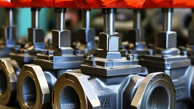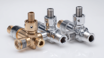

Choosing the right Hydraulic Pressure Regulator in 2026 requires more than comparing prices or connection sizes. The correct device must match pressure range, flow demand, fluid type, temperature, response speed, and installation conditions. A regulator that works smoothly on a clean laboratory bench may behave differently beside a vibrating pump, a warm manifold, or a long steel hose.
Hydraulic educator Brendan Casey explains, “Pressure is a measure of resistance to flow.” This simple observation gives the buying process a practical foundation. A regulator does not create unlimited performance. It manages pressure within the limits of the circuit, components, and operating environment. Small errors matter.
This guide examines selection criteria from an engineering and maintenance perspective. It considers direct-acting and pilot-operated designs, adjustment accuracy, pressure stability, leakage, port configuration, relief protection, and service access. It also addresses datasheet details that buyers sometimes overlook, including rated flow, hysteresis, contamination tolerance, and seal compatibility. In real installations, these details can determine whether a machine cycles quietly or develops heat, noise, and premature wear.
No buying guide replaces a verified system calculation. That limitation deserves attention. Actual performance depends on pump behavior, downstream resistance, fluid cleanliness, and installation quality. Before purchasing, record the normal and maximum pressures, expected flow, fluid temperature, and failure consequences. Then compare those facts with manufacturer documentation and recognized safety practices. A reliable Hydraulic Pressure Regulator should fit the complete system, not merely the shopping list.
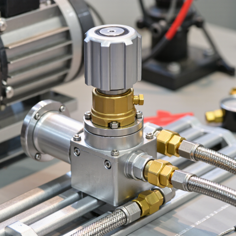
A hydraulic pressure regulator controls fluid pressure before it reaches sensitive components. In most systems, it reduces unstable inlet pressure to a safer, controlled downstream level. The regulator uses a spring, sensing element, and internal valve. A diaphragm or piston measures outlet pressure. When pressure rises above the selected setting, the valve moves toward a closed position. When pressure falls, the valve opens further.
The working principle becomes clearer on a test bench. Imagine 2,000 psi entering the inlet while the actuator requires only 1,200 psi. After adjustment, the spring applies force against the sensing pressure. The valve then balances these forces and restricts flow as needed. A pressure gauge placed downstream helps confirm the actual setting. In practice, the first adjustment is rarely perfect. Temperature, flow demand, and oil viscosity can change the reading.
A reliable buying decision requires more than matching pressure numbers. Check the maximum inlet pressure, regulated range, flow capacity, port size, sealing material, and fluid compatibility. A regulator rated for 10 gallons per minute may respond poorly at higher demand. Contaminated oil can also damage the valve seat and cause pressure drift. I recommend installing suitable filtration and checking pressure under both idle and working conditions. Do not confuse a reducing regulator with a relief valve; they manage pressure differently and protect different parts of a hydraulic circuit.
When comparing hydraulic pressure regulators in 2026, start with pressure range, not purchase price. Check maximum inlet pressure, controlled outlet pressure, and adjustment range under real operating conditions. A regulator rated for 250 bar may behave poorly near its upper limit. Pressure stability matters. Ask for accuracy data at minimum, normal, and peak flow. Narrow tolerance reduces actuator drift and protects seals. Check whether specifications come from tests using oil, water-glycol, or another approved fluid.
Flow capacity deserves equal attention. Compare rated flow, pressure drop, and response time at the same viscosity and temperature. A small body can restrict a fast-moving circuit, creating heat and sluggish movement. Look for port size, connection type, mounting position, and service access. Material compatibility is essential. Steel, stainless steel, and elastomers react differently to hydraulic fluids. Confirm temperature limits and seal compatibility before installation.
During field checks, I inspect gauge ports, lockable adjustment, and contamination control features. A built-in relief function may improve safety, but it should not replace a separate system safeguard. Confirm leakage class, cycle life, and documented test methods. Review maintenance intervals and spare-seal availability before installation. I once focused too heavily on pressure accuracy and overlooked poor access around the adjustment screw. The regulator worked, but calibration became inconvenient. That mistake still influences my selection process. Be careful with headline numbers.
| Regulator Category | Typical Application | Maximum Inlet Pressure | Adjustable Outlet Range | Typical Flow Capacity | Common Port Sizes | Pressure Accuracy | Temperature Range | Common Wetted Materials | Best Buying Consideration |
|---|---|---|---|---|---|---|---|---|---|
| Direct-Acting, Low-Pressure | General hydraulic circuits, compact machinery, and test equipment | Up to 250 bar (3,626 psi) | 5–100 bar (73–1,450 psi) | Approximately 20–80 L/min | G 1/4, G 3/8, G 1/2; SAE sizes available | Typically ±3–5% of set pressure | −20°C to +80°C (−4°F to +176°F) | Steel or cast iron body, hardened steel spool, nitrile seals | Choose a pressure range that places the normal setting near the middle of the adjustment span. |
| Pilot-Operated, High-Flow | Presses, injection machinery, mobile equipment, and continuous-duty systems | Up to 350 bar (5,076 psi) | 20–315 bar (290–4,570 psi) | Approximately 100–500 L/min | G 1/2–G 1 1/2; SAE and flange connections | Typically ±1–3% of set pressure | −20°C to +80°C (−4°F to +176°F) | Ductile iron or steel body, alloy steel internals, oil-resistant seals | Verify rated flow at the required pressure drop; high flow can cause heat and noise if undersized. |
| Pressure-Reducing Valve | Protecting a lower-pressure branch from a higher-pressure supply | Up to 420 bar (6,092 psi) | 10–350 bar (145–5,076 psi) | Approximately 30–300 L/min | G 1/4–G 1; SAE ports and manifold mounting | Typically ±2–5% with stable flow | −20°C to +80°C (−4°F to +176°F) | Steel body, hardened poppet or spool, NBR or FKM seals | Check the minimum pressure differential required for stable regulation. |
| Sequence Pressure Regulator | Controlling the order of multiple hydraulic operations | Up to 350 bar (5,076 psi) | 15–300 bar (218–4,351 psi) | Approximately 20–200 L/min | G 1/4–G 1; SAE and subplate mounting | Typically ±3–5% of set pressure | −20°C to +80°C (−4°F to +176°F) | Steel or iron body, stainless spring, nitrile or FKM seals | Confirm drain, pilot, and outlet connections for the intended circuit sequence. |
| Proportional Pressure Regulator | Automated machinery, robotics, and variable-force control systems | Up to 315 bar (4,569 psi) | 5–250 bar (73–3,626 psi) | Approximately 10–150 L/min | G 1/4–G 3/4; SAE and manifold options | Typically ±1–3% of full scale | −20°C to +70°C (−4°F to +158°F) | Steel body, precision spool, electronic transducer, FKM seals | Compare command signal, hysteresis, response time, and electrical protection rating. |
| Cartridge Pressure Regulator | Compact manifolds, custom blocks, and space-limited installations | Up to 350 bar (5,076 psi) | 10–315 bar (145–4,570 psi) | Approximately 15–250 L/min | Standard cartridge cavities; external ports determined by manifold | Typically ±2–5% of set pressure | −30°C to +100°C (−22°F to +212°F), seal dependent | Hardened steel cartridge, aluminum or steel manifold, NBR/FKM seals | Match the cartridge cavity standard, installation torque, and service access requirements. |
| Relief-Type Pressure Regulator | Overpressure protection and limiting maximum system pressure | Up to 420 bar (6,092 psi) | 20–400 bar (290–5,802 psi) | Approximately 20–400 L/min | G 1/4–G 1 1/2; SAE and flange connections | Cracking pressure commonly ±5% | −20°C to +80°C (−4°F to +176°F) | Steel or iron body, hardened poppet, spring steel, NBR/FKM seals | Size the return line and tank connection to handle full relief flow safely. |
Choosing the right hydraulic pressure regulator starts with the system’s real operating conditions, not its maximum rating. Record normal pressure, peak pressure, flow demand, fluid temperature, and cylinder speed. A regulator rated too low may drift or fail early. One rated far above the working range can provide poor adjustment control. In field inspections, I also check pressure at the actuator, not only at the pump. Pressure losses in long hoses can change the selection.
Match the regulator’s flow capacity to the highest expected demand. Confirm port size, connection type, adjustment range, and compatibility with the hydraulic fluid. Direct-acting models suit simpler circuits and quick response. Pilot-operated models often handle larger flows with steadier control. Keep contamination in mind. A fine internal passage can react badly to dirty fluid, even when the valve appears correctly sized.
Installation details matter more than many buyers expect. Provide a readable gauge near the regulated outlet, protect the adjustment mechanism, and follow the specified flow direction. Test the system at low pressure before applying full load. I once found unstable pressure caused by a restricted return line, not the regulator itself. That mistake was avoidable. Recheck settings after the oil reaches operating temperature, because viscosity changes can affect response. Leave room for maintenance, since a regulator buried behind rigid tubing becomes difficult to inspect safely.
2026 Best Hydraulic Pressure Regulator Buying Guide: Installation, Adjustment, and Compatibility Requirements
A hydraulic pressure regulator protects downstream components from unstable pressure. Installation starts with the circuit diagram, not the wrench. ISO 4413:2010 emphasizes safe pressure control, isolation, and clearly accessible relief arrangements. Mount the regulator in the correct flow direction. Keep the body supported, especially near vibrating pumps. Contamination is a quiet failure source. Flush pipes, cap open ports, and use filtration suited to the fluid.
Compatibility needs measured evidence. Check maximum inlet pressure, regulated range, flow capacity, port size, seal material, fluid type, and operating temperature. A 2024 global hydraulic equipment market analysis estimated the sector at more than 40 billion U.S. dollars, showing how varied equipment requirements have become. That scale does not make every regulator interchangeable. A compact machine may need fine low-flow control, while a press requires stable performance during pressure spikes. Similar threads can still leak.
Adjustment should begin below the target setting. Install a calibrated downstream gauge, open the circuit gradually, and turn the adjustment mechanism in small increments. Cycle the actuator several times, then recheck pressure at operating temperature. Do not adjust against a closed, unverified circuit. My earlier installations taught me this: a cold reading can look perfect. It may drift later. Record inlet pressure, outlet pressure, flow, temperature, and final setting. The record is often more useful than memory.
A hydraulic pressure regulator needs routine care, not occasional attention. NFPA’s 2024 State of the Industry reporting continues to identify contamination control and component reliability as major fluid-power concerns. Inspect the regulator body for oil stains, cracked fittings, and loose mounting hardware. Check pressure at operating temperature, because cold oil can create a misleadingly high reading. Use a calibrated gauge.
Filter condition deserves closer attention. ISO 4406:2021 classifies hydraulic cleanliness by particle counts at 4, 6, and 14 micrometres. Record the cleanliness code during scheduled sampling. Compare it with the equipment manufacturer’s target, rather than guessing. A dark filter indicator is useful, but it is not a laboratory result. Replace blocked elements with the correct rating, and keep replacement seals clean and lightly lubricated.
Common symptoms need structured checks. If downstream pressure drops, inspect the inlet supply, adjustment spring, pilot passage, and relief path. If pressure surges, look for air, unstable flow, or a sticking spool. A regulator that creeps upward may have internal leakage or contamination under its seat. I have seen technicians adjust the set screw before checking the gauge. That saves minutes, sometimes. It can also hide the real fault. Log pressure, temperature, filter changes, and observed symptoms after every service visit. These records support repeatable decisions and align maintenance practice with ISO 4413 safety principles.